

Trigeneration schemes: atlas of schemes and Thermax factory diagrams
In brief. A scheme shows where the engine heat comes from, where it goes and where the chiller sits. Here is our atlas, and below it the Thermax factory diagrams, the English ones with their labels explained.
A trigeneration (CCHP) scheme answers three questions: where the engine heat comes from, through which circuit it reaches the lithium bromide absorption chiller, and where the chilled water and the chiller's heat go. Below is our atlas of schemes by engine type, followed by factory diagrams from the Thermax catalog: with Russian and English labels, with the labels explained. If you are not yet familiar with how it works, the principle is covered in the article "How a trigeneration plant works".
How to read the schemes?
The atlas schemes use four line colors: orange-red means hot water, brown-gray exhaust gases, blue chilled water, and turquoise cooling water, that is, the cooling tower circuit. A blue frame marks what belongs to the cooling circuit: the chiller, the cooling tower, water treatment and controls. The engine, boiler and electrical part stay outside the frame. The figures on the schemes are typical: the chiller COP, water temperatures of 7/12 °C, heat rejection to the cooling tower per 1 kW of cooling. For your site they are calculated again.
What to look at. Where the scheme has a diverter damper, the exhaust can bypass the chiller. Where there are emergency radiators, the engine does not depend on the chiller. Where there is a tank or an NCT chiller, there is backup cooling. These three points show whether the plant will survive a chiller shutdown. More on where schemes break down: "Why trigeneration does not pay back".
Where to start the choice?
Four questions. If the answer to all of them is "yes," trigeneration is worth calculating.
-
Is there gas and a gas allocation? If there is no gas, the choice is between a diesel plant (diesel) and an electric chiller.
-
Is the grid expensive, or can it not provide the capacity? If the grid is cheap, a chiller or an absorption chiller running on waste heat you already have is enough.
-
Are cooling and heat needed for 3,000–4,000 hours a year or more? If the load is short, the engine will be running into its radiators.
-
Is more than 300 kW of cooling needed? If less, a chiller is usually more cost-effective.
Next comes the choice of engine: gas engines for sites up to 10 MW, a gas turbine for multi-megawatt plants, microturbines for buildings and data centers, steam where a process needs it, biogas and fuel cells for special cases. A comparison table of engines is on the "Types of trigeneration" page, and a calculation for your site: feasibility study.
Trigeneration: one gas supply, three kinds of energy
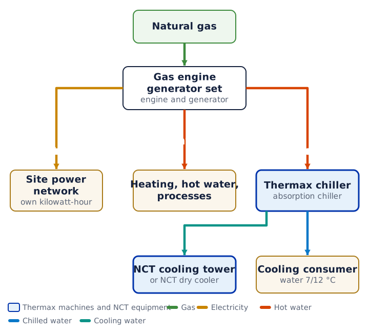
Gas goes into a gas engine. It produces electricity and heat. The heat goes to space heating and into a Thermax absorption chiller, which makes cooling; an NCT cooling tower rejects the chiller's heat.
Where a megawatt of gas goes in a gas engine
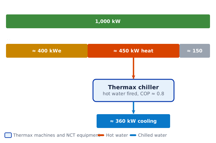
From 1,000 kW of gas, a gas engine produces about 400 kW of electricity and about 450 kW of heat; about 150 kW is lost. An absorption chiller with a COP of 0.8 turns 450 kW of heat into about 360 kW of cooling.
Summer: cogeneration vs trigeneration
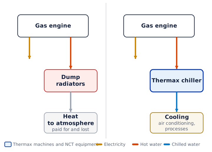
Left, cogeneration: in summer the engine heat has nowhere to go and is dumped to atmosphere by radiators. Right, trigeneration: the same heat goes into an absorption chiller and becomes cooling.
Where gas engine heat goes in each season
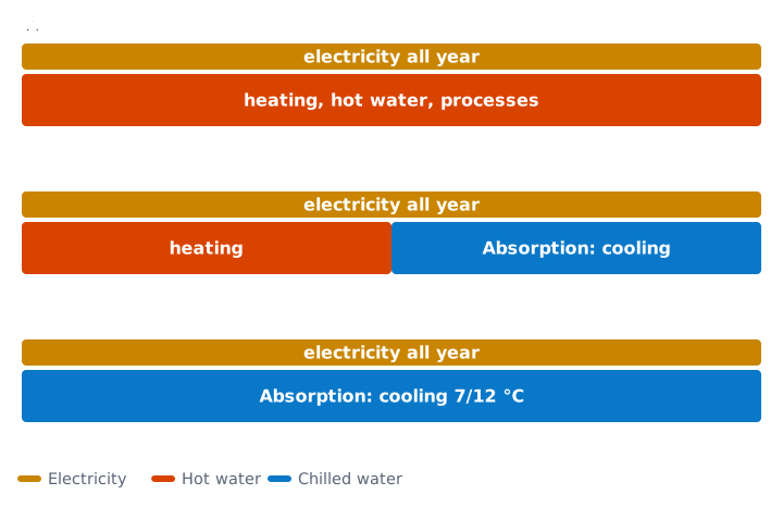
In winter the heat goes to space heating, hot water and processes; in the shoulder season it is split between heating and the absorption chiller; in summer it goes into the chiller and produces 7/12 °C water. The site gets electricity all year round.
The classic: gas engine and hot water absorption chiller
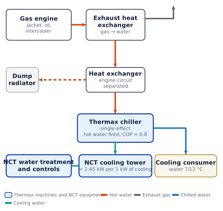
The engine jacket and exhaust heat exchanger heat water to about 90 °C. The water goes through a heat exchanger into a single-effect Thermax chiller with a COP of about 0.8. The chiller supplies 7/12 °C water to the consumer and rejects heat to an NCT cooling tower. Surplus heat is removed by dump radiators.
Twice the cooling: exhaust straight into the chiller
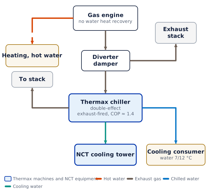
Exhaust gas goes through a diverter damper straight into a double-effect Thermax chiller with a COP of about 1.4. When cooling is not needed, the damper sends the gas to the bypass. Hot water from the engine jacket goes to space heating.
Trigenie: exhaust and jacket water in one machine
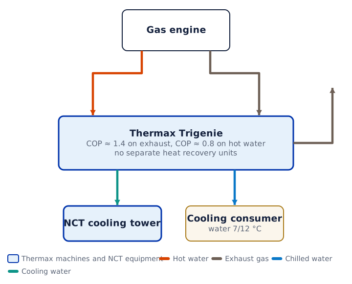
The Thermax Trigenie machine takes two sources at once: exhaust gas with a COP of about 1.4 and jacket hot water with a COP of about 0.8. No separate heat recovery units are needed. The output is 7/12 °C water.
Steam from a heat recovery steam generator
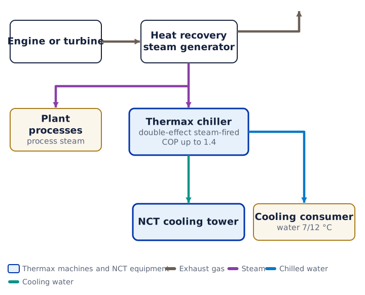
Engine exhaust passes through a heat recovery steam generator. The steam goes to the plant's processes and into a double-effect steam-fired Thermax chiller. Suits a plant that needs steam.
Gas turbine and exhaust-fired chiller
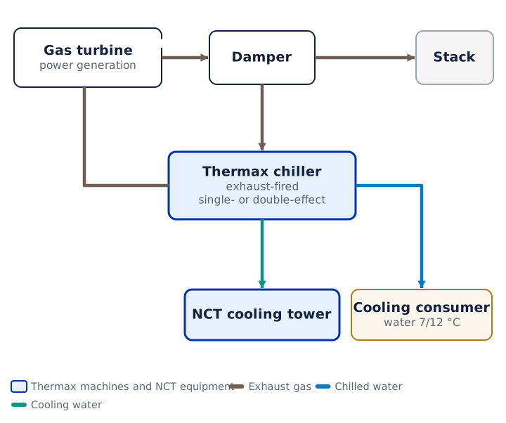
Gas turbine exhaust goes through a damper into an exhaust-fired Thermax chiller; when little cooling is needed, the gas goes to the bypass. The turbine gives a lot of high-temperature heat. The chiller supplies water to the consumer and rejects heat to an NCT cooling tower.
Gas turbine, heat recovery steam generator, steam and district heating
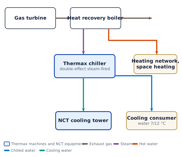
A heat recovery steam generator sits after the turbine. It supplies steam to a steam-fired Thermax chiller and hot water to the heating network. One source covers both heat and cooling.
Microturbines and an absorption chiller
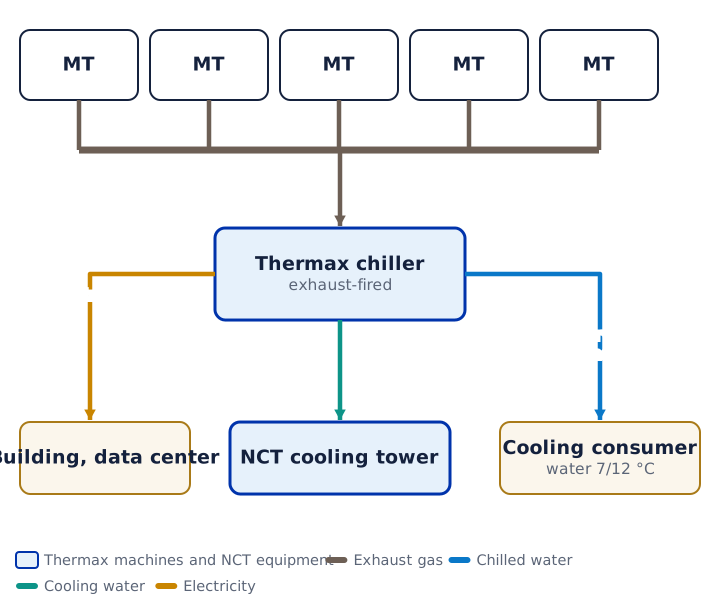
Several microturbines produce electricity; their exhaust is collected in a common header and goes into an exhaust-fired Thermax chiller. The scheme is used in buildings and data centers.
Diesel power plant: the heat works too
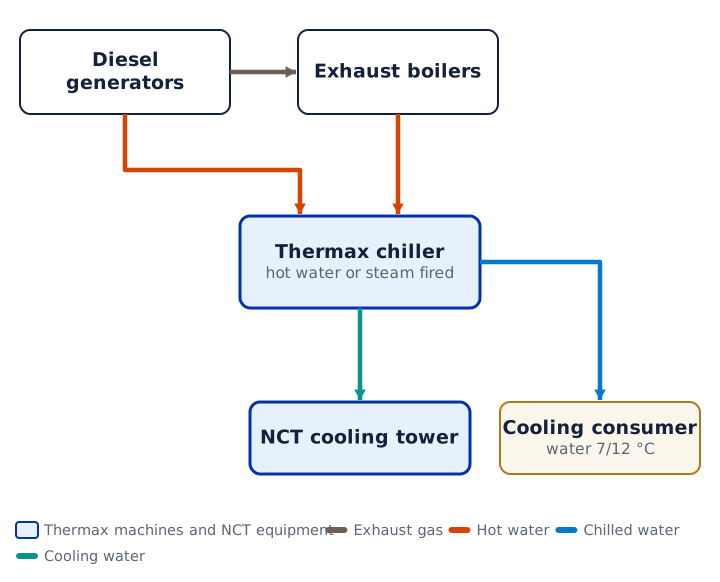
Diesel generators send their exhaust to heat recovery boilers. Hot water or steam goes into Thermax chillers, and jacket cooling water can also feed one of them. Used where there is no gas.
Biogas and other non-conventional fuels
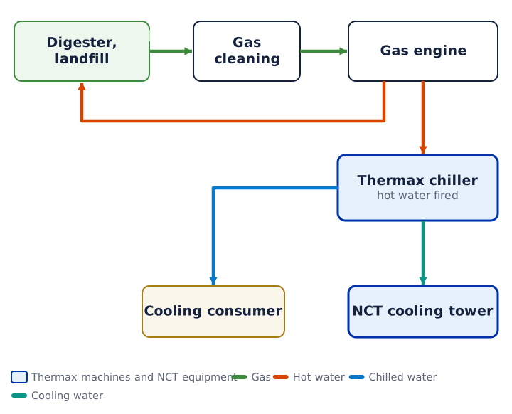
Biogas goes into a gas engine after cleaning. Part of the heat returns to the digester, the rest goes into a Thermax chiller. Heat that would otherwise be lost produces cooling.
Chiller with a burner: cooling even without the engine
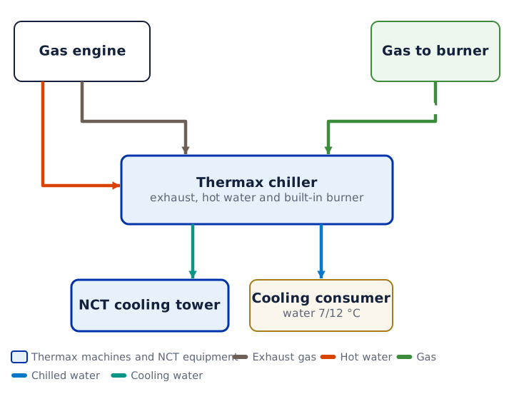
The Thermax machine takes exhaust, hot water and gas for its built-in burner. When the engine is stopped or heat is short, the burner tops up to the required cooling and the consumer keeps its cooling.
Two heat sources: gas engine and boiler house
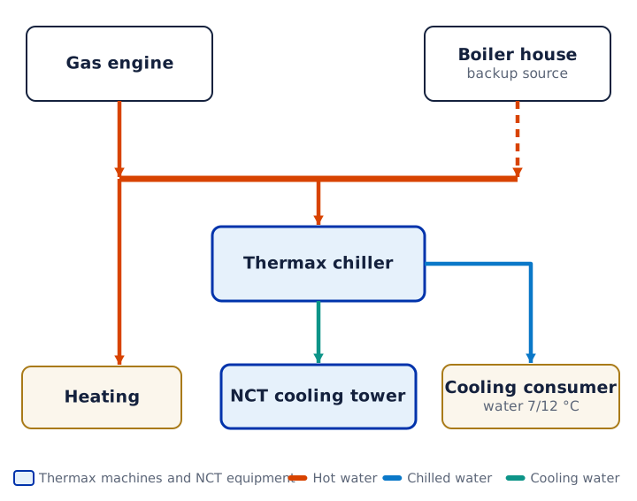
The hot water header is fed by the gas engine and by the boiler house. The Thermax chiller gets heat even when the engine is stopped. This scheme runs at a greenhouse complex in the Sverdlovsk Region.
Absorption chiller carries the base, electric chiller takes the peak
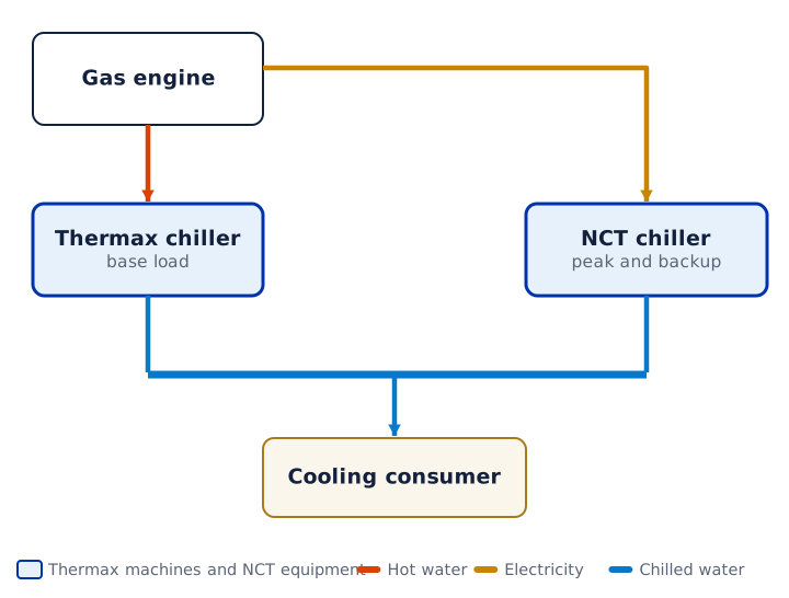
The Thermax chiller runs continuously on the base load using engine heat. An NCT chiller comes on for the peak and as a backup. Both machines feed a common chilled water header.
Chilled water storage for the changeover
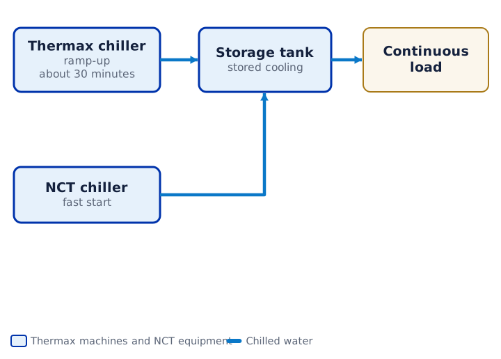
An absorption chiller takes about 30 minutes to reach full output, so a chilled water storage tank is installed for a continuous load. It carries the consumer while the chiller starts or switches to another source.
How to reject heat: cooling tower or dry cooler
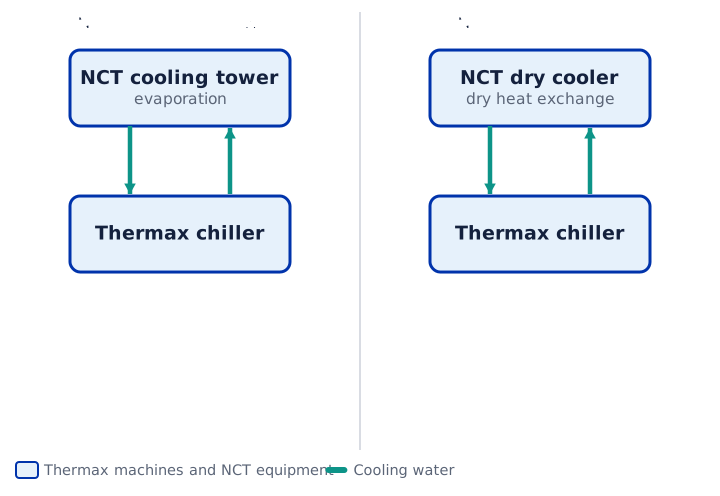
Left, an open or closed-circuit NCT cooling tower: colder water, the chiller gives more cooling, but water treatment and make-up water are needed. Right, a dry NCT dry cooler: no water, but higher temperature and a larger footprint.
How much heat has to be rejected
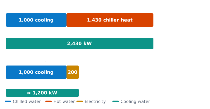
At 1,000 kW of cooling, an absorption chiller takes in 1,430 kW of heat and rejects 2,430 kW to the cooling tower. An electric chiller with a COP of 5 rejects about 1,200 kW at the same capacity. That is why the cooling tower in an absorption scheme is almost twice as large.
Exhaust path: where back pressure is calculated
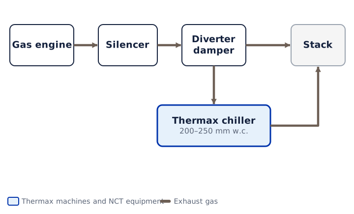
Exhaust goes from the engine through the silencer and diverter damper into the chiller and the stack. The chiller's gas-side resistance of 200–250 mm water column is added to the ducts, damper and silencer. The total must not exceed the engine's allowable back pressure. If the chiller stops or power fails, the damper goes to bypass.
How an absorption chiller makes cooling from heat
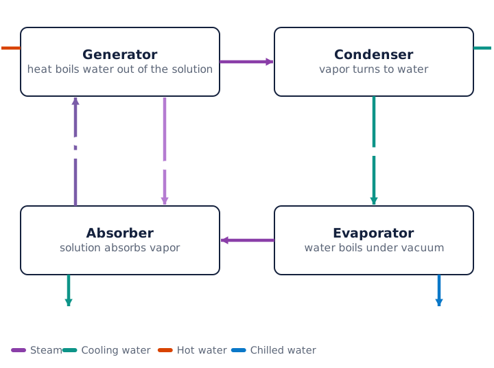
The generator boils water out of the lithium bromide solution using external heat. The vapor condenses in the condenser; the water boils under vacuum in the evaporator and takes heat from the consumer's water. The vapor is absorbed by the strong solution in the absorber, and a pump returns the weak solution to the generator.
Data center: what about redundancy
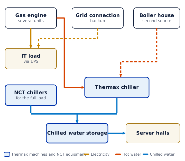
Gas engines feed the IT load, and their heat goes into Thermax chillers. A gas engine failure knocks out both electricity and heat at once, so a grid connection, a second heat source or NCT chillers sized for the full load, plus chilled water storage, are needed.
Greenhouse complex: CO₂ as well
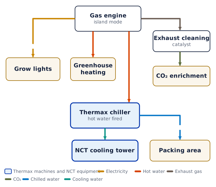
A typical greenhouse scheme: gas engines provide grow lights and heating, cleaned exhaust supplies CO₂ to the plants, and hot water through a Thermax chiller cools the packing area. This is how a greenhouse plant in the Sverdlovsk Region gets cooling down to 3.5 °C.
Turbine inlet cooling: more power in summer
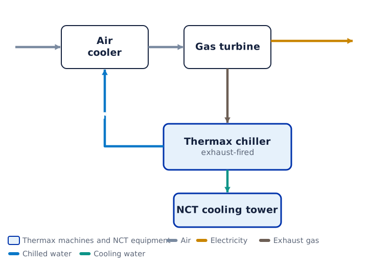
In hot weather a gas turbine loses power. The exhaust drives an absorption chiller, and its chilled water cools the air at the turbine compressor inlet. Summer electrical output rises thanks to the turbine's own waste heat.
Absorption heat pump: heat from cooling water
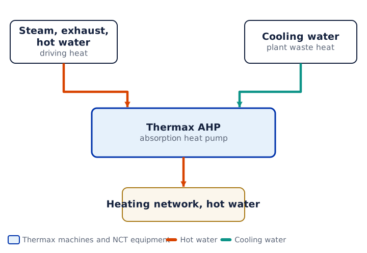
A Thermax absorption heat pump takes high-temperature heat from exhaust or steam and extracts low-grade heat from cooling water. More heat goes out to the heating network than the source provided, and the cooling water is cooled without a cooling tower.
Where trigeneration fails: six interfaces
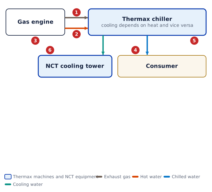
The six places where mistakes are made most often: exhaust back pressure, engine jacket overheating when the chiller stops, return temperature, engine loading and cooling demand out of step, crystallization on power failure, untreated cooling tower water. All of them sit at the interface between generation and the cooling circuit.
Jacket water circuit: the engine comes first
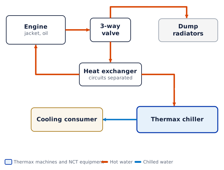
A three-way valve holds the return temperature to the engine. The engine circuit is separated from the chiller circuit by a heat exchanger. If the chiller does not take the heat, the valve sends it to the dump radiators and the engine keeps running.
Is trigeneration right for your site: four questions
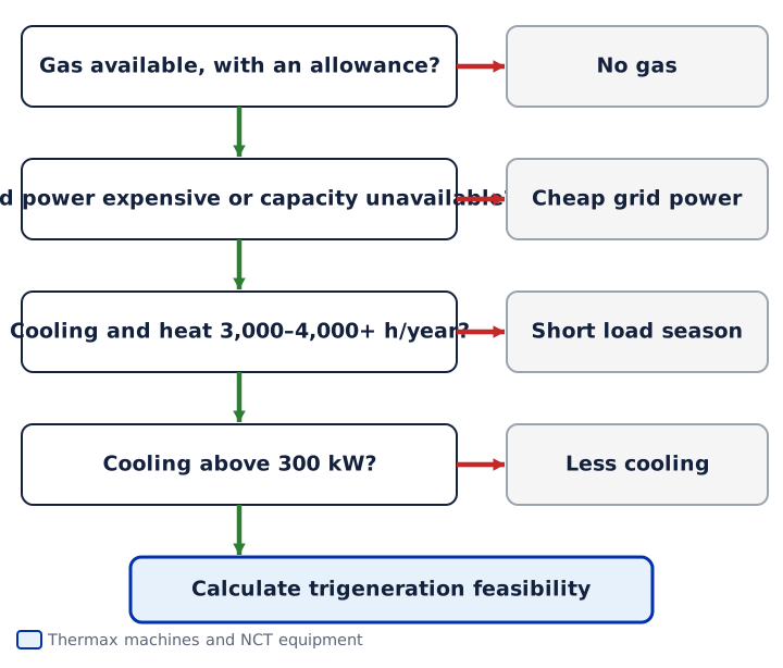
Four questions: is there gas and a gas allowance; is electricity expensive or does the grid not provide the capacity; are cooling and heat needed for 3,000–4,000 hours a year or more; is the cooling load above 300 kW. Four yes answers mean trigeneration is worth calculating, otherwise other schemes.
Separate supply vs trigeneration
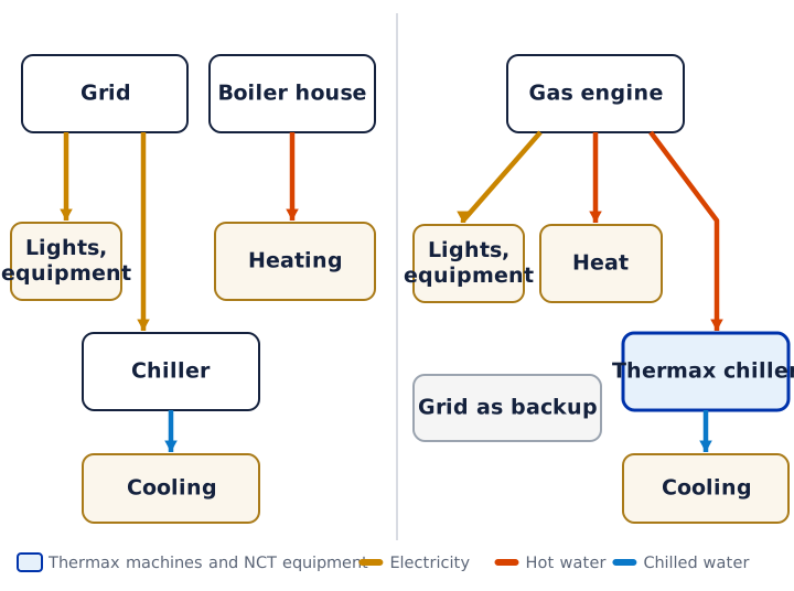
With separate supply, the site buys electricity from the grid, gets heat from a boiler house and makes cooling with a chiller on the same grid electricity. With trigeneration, one plant on one gas supply makes all three kinds of energy, and the grid stays as a backup.
Grid-parallel or island
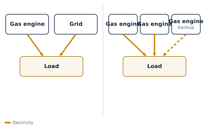
In grid-parallel operation, the plant and the grid supply the load together, and the grid covers peaks and backup. In island mode there is no grid: the plant holds frequency and voltage itself, and the number of units is chosen with a margin for the failure of one.
Thermax diagrams
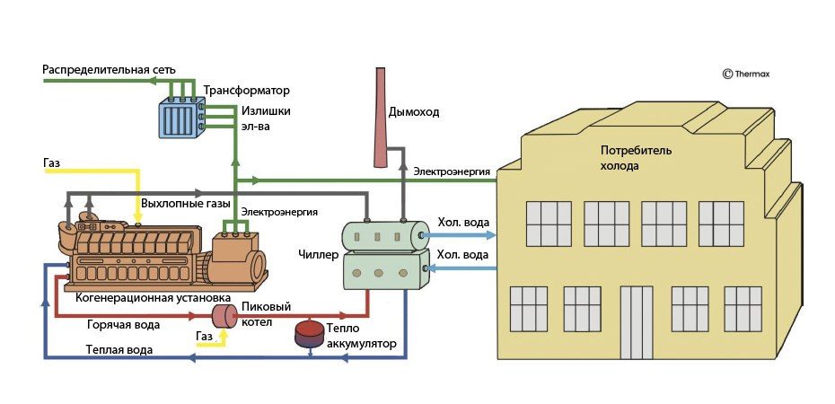
Cogeneration plant and chiller: chilled water to the consumer
The engine gives the chiller its exhaust and hot water, the cooling tower removes the heat, and the consumer gets chilled water and electricity.
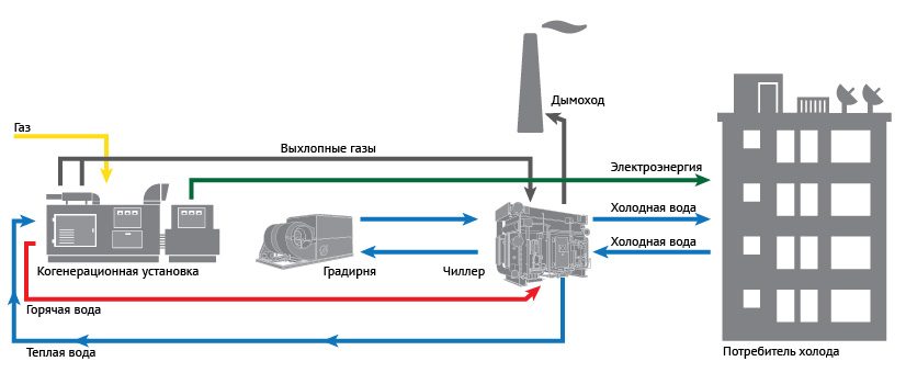
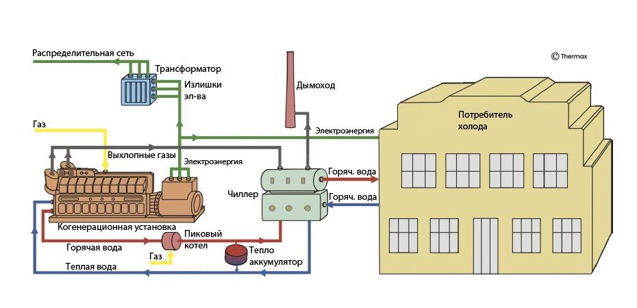
The same scheme: hot water to the consumer
The chiller works as a heater, and the consumer gets hot water from it.
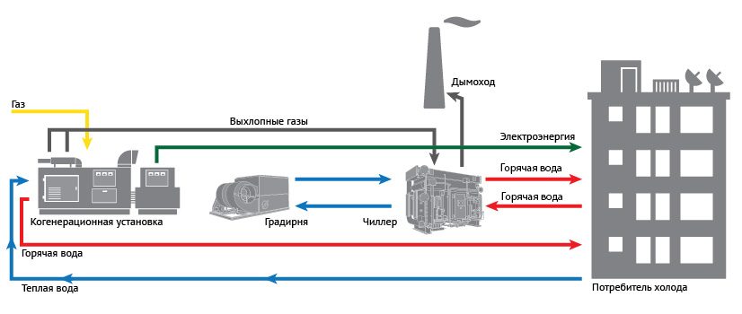
These are diagrams from the manufacturer's catalogs and presentations. They show how Thermax draws the connection options and help you match your site to a typical one. The labels on the English diagrams are explained below each one.
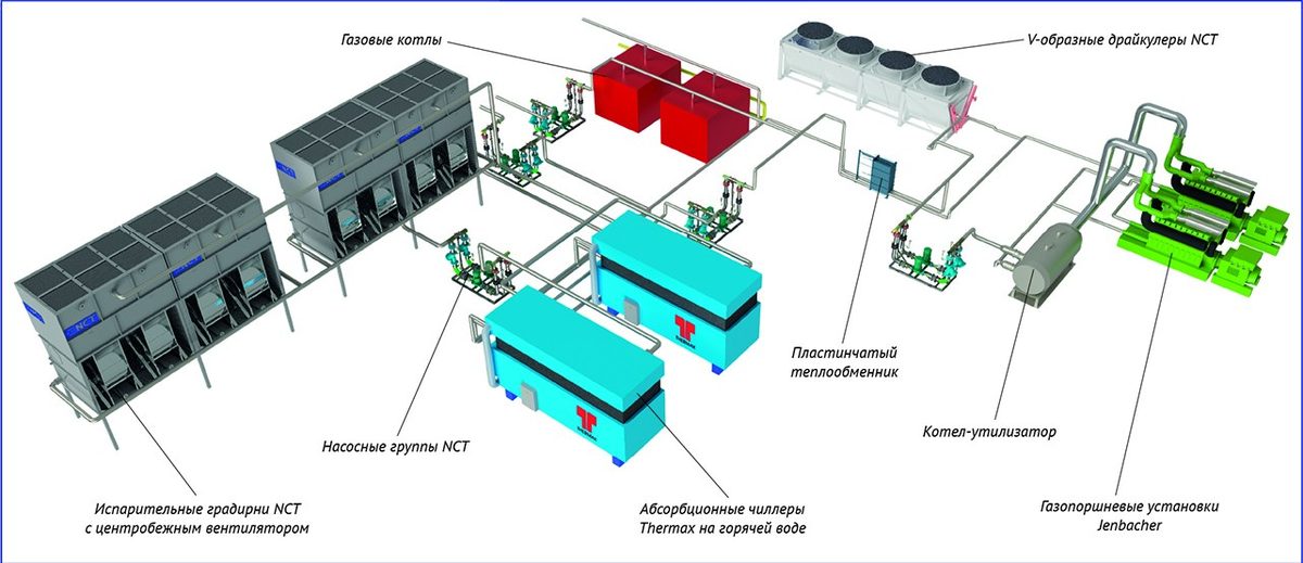
NCT and Thermax complex: gas engines, heat recovery boiler, cooling towers and dry coolers
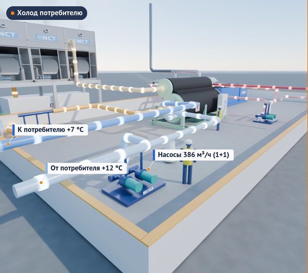
A 3D diagram of the complex. On the right are Jenbacher gas engine generator sets, next to them a heat recovery boiler and a plate heat exchanger. Hot water goes to two hot water Thermax absorption chillers. The chillers' heat goes to NCT evaporative cooling towers with centrifugal fans, and next to them stand NCT V-type dry coolers. Between them are NCT pump skids, and at the top gas boilers as a second heat source.
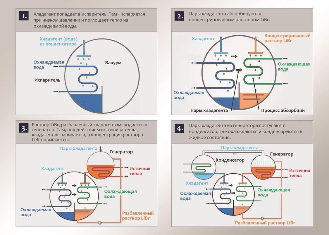
How an absorption chiller makes cooling: a four-step cycle
A lithium bromide chiller operates under vacuum. In the first step the refrigerant (water) evaporates in the evaporator and takes heat from the water being chilled. In the second, the refrigerant vapor is absorbed by concentrated lithium bromide solution in the absorber. In the third, the diluted solution is heated by the heat source in the generator, the refrigerant boils off, and the solution concentration rises. In the fourth, the refrigerant vapor condenses in the condenser, which is cooled by cooling tower water. The cycle is closed.
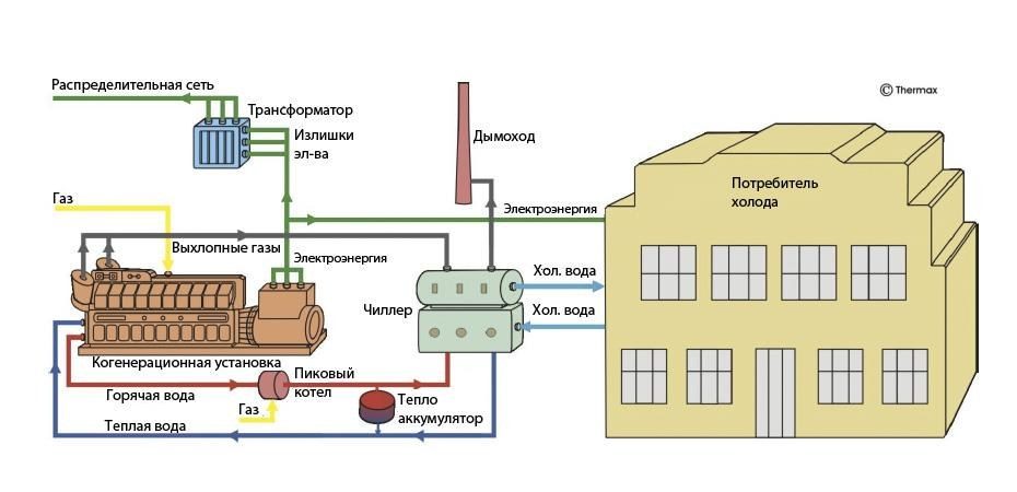
Basic scheme: engine, chiller, cooling consumer
Gas goes to the cogeneration plant. The consumer gets the electricity, and the surplus goes through a transformer to the distribution grid. Exhaust gases and engine hot water go to the chiller (two stages), and the chiller supplies chilled water to the consumer. A peak boiler and a heat storage tank maintain the heat balance. The remaining exhaust goes to the chimney.
Option 1: chilled water from the chiller
The first of seven options in the Thermax series. The drawing matches the basic scheme: the consumer gets chilled water, and electricity and heat follow the same lines.
Option 2: the chiller supplies hot water
In this scheme the chiller works as a heater: the consumer gets hot water from it, not chilled water. This connection is used when the consumer needs heat, not cooling.
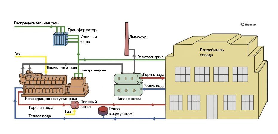
Option 3: chiller-heater with hot water
Here the scheme shows a chiller-heater (a unit that combines cooling and heating), and hot water goes to the consumer from it. A second hot water line comes directly from the engine circuit through the peak boiler.
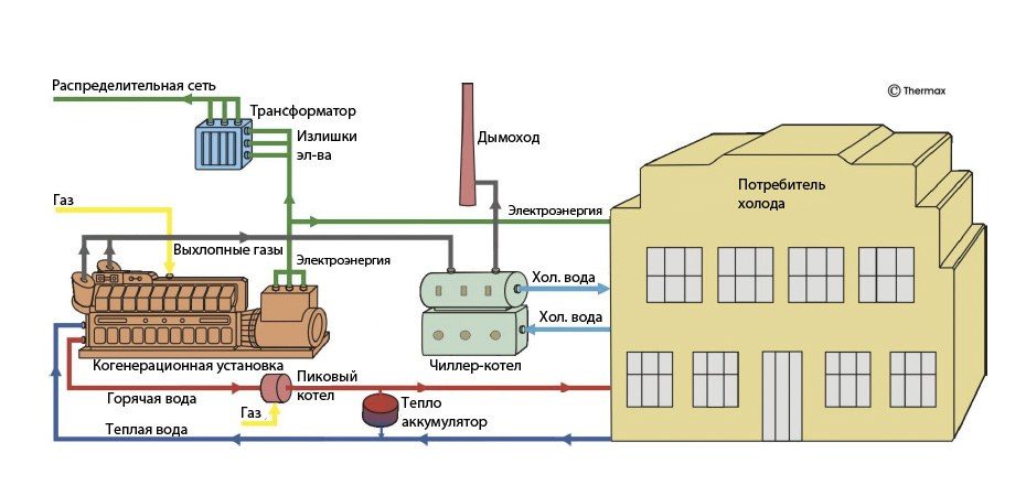
Option 4: chiller-heater with chilled water
The same combination, but the chiller-heater supplies chilled water to the consumer. Hot water from the engine circuit and the peak boiler still goes to the consumer directly. One site gets both cooling and heat.
Option 5: biogas and chilled water
Biogas from the reservoir goes to the engine, the reactor (digester) is heated by the engine jacket, and the chiller supplies chilled water to the consumer. Details are on the biogas page.
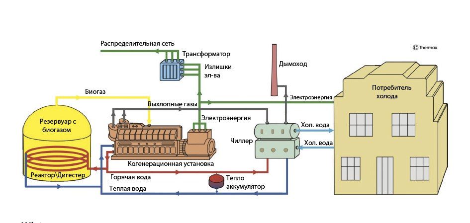
Option 6: biogas and hot water
The same engine and reactor, but the chiller runs in heating mode and supplies hot water to the consumer.
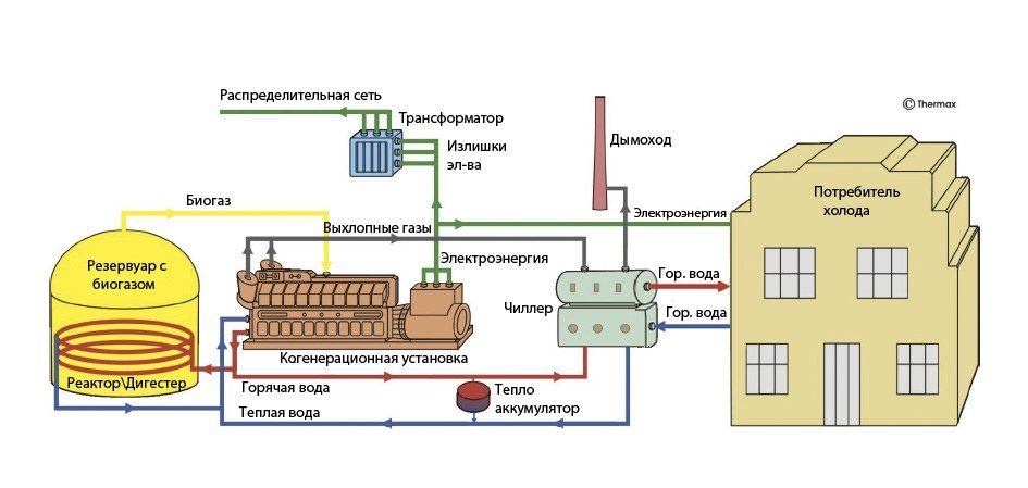
Option 7: biogas, hot water directly
Hot water goes to the consumer both from the chiller and directly from the engine circuit.
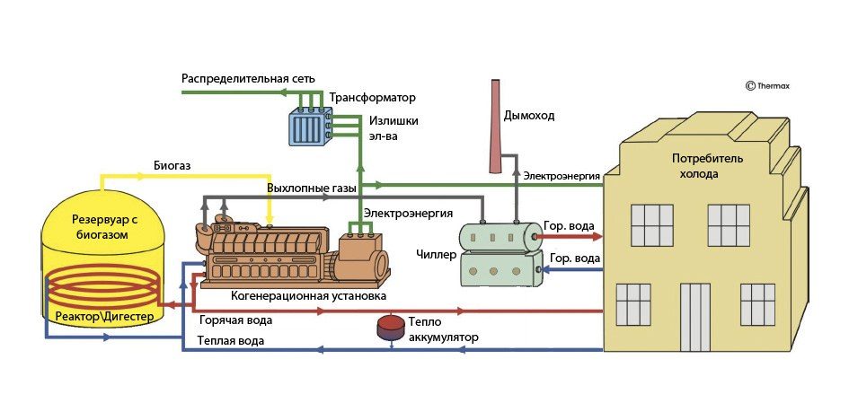
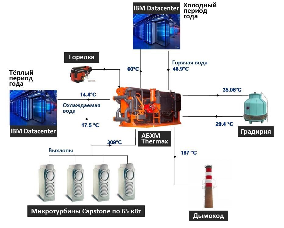
Microturbines and a data center: warm and cold seasons
Four 65 kW Capstone microturbines send their exhaust (309 °C) to a Thermax chiller. In the warm season the chiller makes chilled water at 17.5/14.4 °C for the data center, and in the cold season it delivers heat as hot water at 60/48.9 °C. The cooling tower operates at 29.4/35.06 °C, the exhaust leaves to the chimney at 187 °C, and a burner tops up the capacity when there is not enough heat.
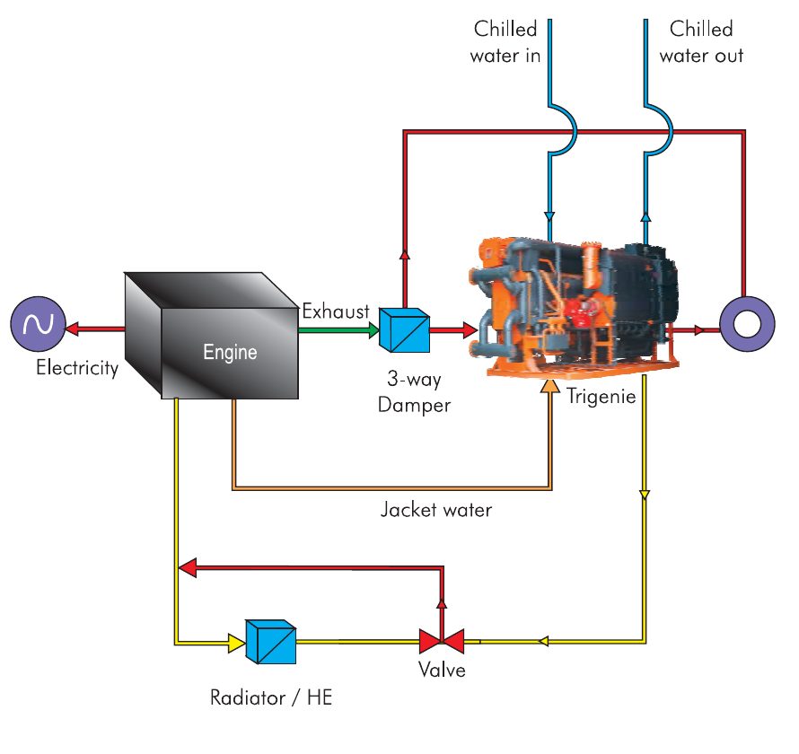
The Trigenie principle: exhaust and jacket water in one chiller
The engine generates electricity. Its exhaust goes through a three-way damper into the Trigenie chiller, and the jacket water goes there too through a separate circuit. Surplus jacket heat is removed by a radiator or heat exchanger through a valve. Chilled water leaves the chiller to the consumer.
| Label on the diagram | Meaning |
|---|---|
| Engine | engine |
| Electricity | electricity |
| Exhaust | exhaust gases |
| 3-way Damper | three-way damper |
| Trigenie | Thermax Trigenie chiller |
| Jacket water | engine jacket water |
| Radiator / HE | radiator or heat exchanger |
| Valve | valve |
| Chilled water in / out | chilled water at the inlet and outlet |
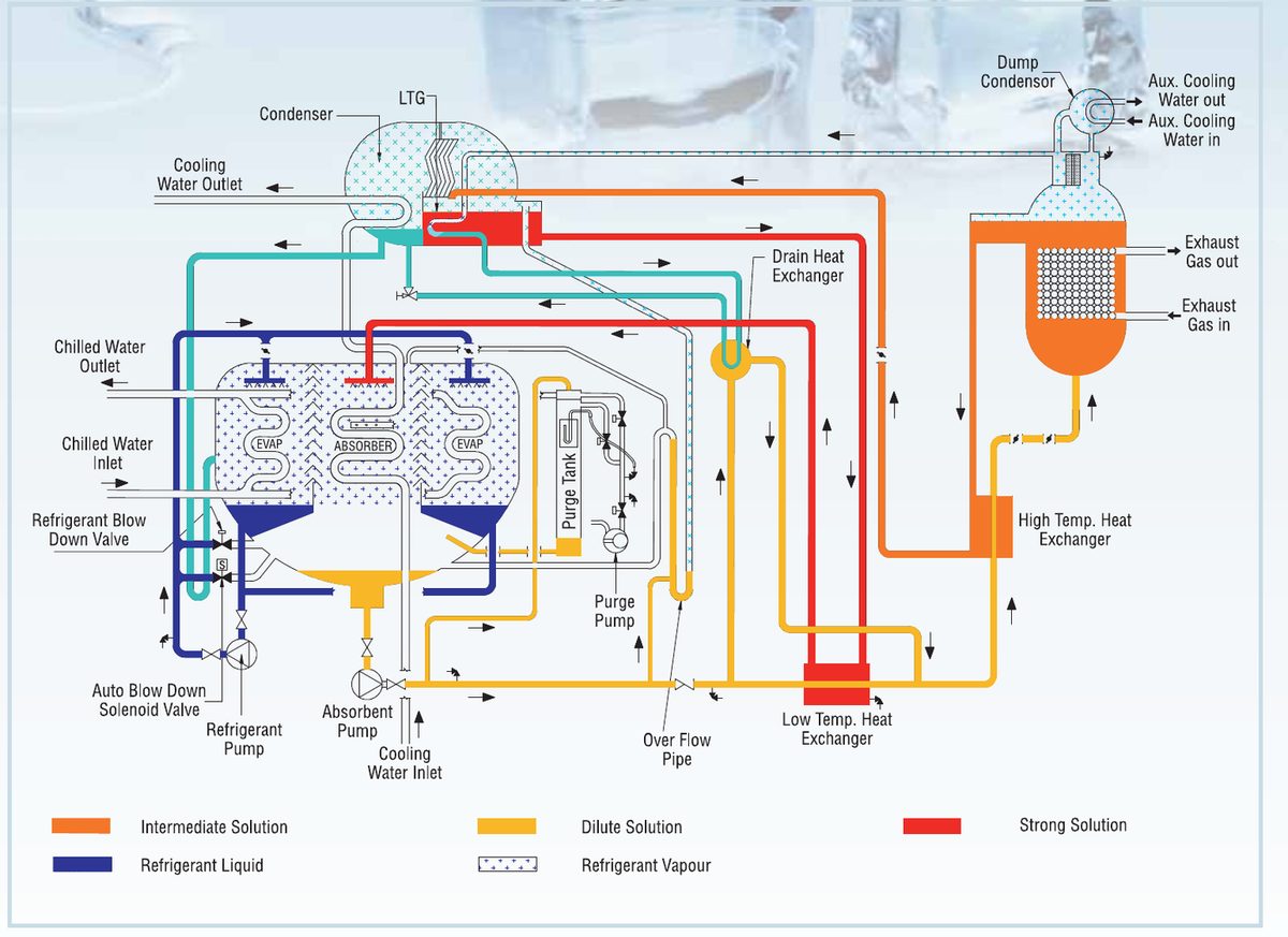
Cycle of an exhaust-fired chiller (Trigenie)
A diagram of the flows inside the chiller. The exhaust passes through the vessel on the right and leaves cooled. The solutions flow through circuits between the generator, absorber and heat exchangers. The dump condenser protects the chiller during shutdown.
| Label on the diagram | Meaning |
|---|---|
| Exhaust Gas In / Out | exhaust gases at the inlet and outlet |
| High Temp. Heat Exchanger | high-temperature solution heat exchanger |
| LTG | low-temperature generator |
| Condenser | condenser |
| EVAP | evaporator |
| ABSORBER | absorber |
| Low Temp. Heat Exchanger | low-temperature solution heat exchanger |
| Drain Heat Exchanger | drain heat exchanger |
| Dump Condenser | dump condenser |
| Aux. Cooling Water In / Out | auxiliary cooling water at the inlet and outlet |
| Cooling Water Inlet / Outlet | cooling water (to the cooling tower) at the inlet and outlet |
| Chilled Water Inlet / Outlet | chilled water at the inlet and outlet |
| Absorber Pump | solution pump |
| Refrigerant Pump | refrigerant pump |
| Purge Tank, Purge Pump | air purge tank and pump |
| Refrigerant Blow Down Valve, Auto Blow Down Solenoid Valve | refrigerant blowdown valves |
| Over Flow Pipe | overflow pipe |
Flow colors follow the legend at the bottom of the diagram: Intermediate Solution (solution of intermediate concentration), Dilute Solution (diluted solution), Strong Solution (concentrated solution), Refrigerant Liquid (liquid refrigerant), Refrigerant Vapour (refrigerant vapor).
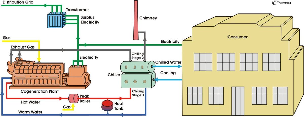
Application 1: cooling only, all year round
An engine and a chiller with two cooling stages. The first stage runs on jacket hot water, the second on exhaust. The consumer gets chilled water; this scheme provides no heat for space heating.
| Label on the diagram | Meaning |
|---|---|
| Cogeneration Plant | cogeneration plant |
| Gas | gas |
| Exhaust Gas | exhaust gases |
| Chimney | chimney |
| Hot Water / Warm Water | hot and warm water (supply and return of the engine circuit) |
| Peak Boiler | peak boiler |
| Heat Tank | heat storage tank |
| Chiller, Chilling Stage 1 / Stage 2 | chiller, first and second cooling stages |
| Chilled Water / Cooling | chilled water to the consumer and return water |
| Transformer, Distribution Grid | transformer, distribution grid |
| Surplus Electricity | surplus electricity |
| Consumer | consumer |
Application 2: in summer, exhaust to the chiller-heater
In this scheme the exhaust goes to a chiller-heater (Chiller Heater), and the engine hot water goes directly to the consumer through the peak boiler. The labels are the same as in Application 1, plus Chiller Heater, a unit that can provide both cooling and heat.
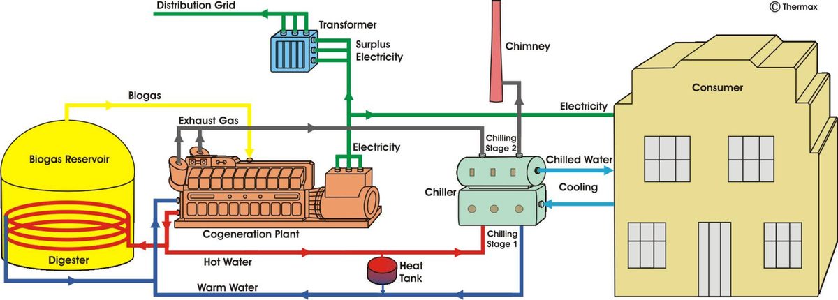
Application 4: biogas and reactor
A biogas plant. The diagram has new labels: Biogas Reservoir (biogas reservoir), Digester (reactor, digester), Biogas (biogas). Part of the jacket heat goes back to the reactor, and the rest, together with the exhaust, goes to a chiller with two stages.
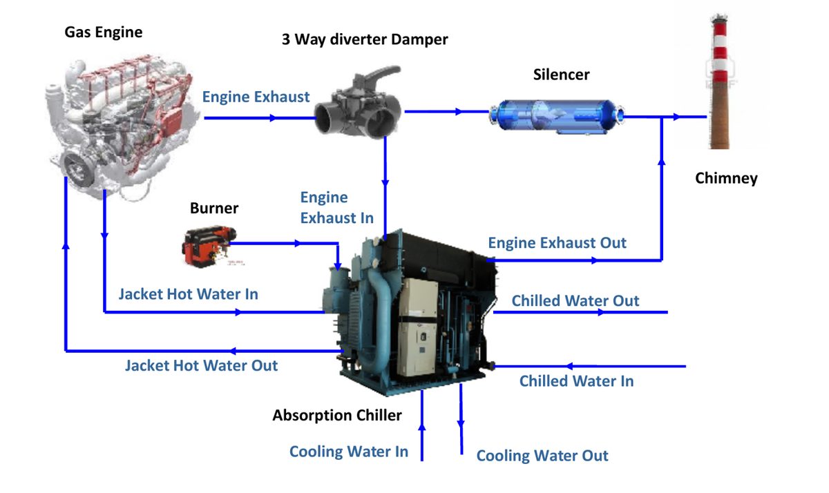
Engine, damper, burner and chiller
A gas engine sends its exhaust to a three-way diverter damper. The damper directs the gas either into the chiller or past it through a silencer to the chimney. The burner provides backup when the engine heat is not enough.
| Label on the diagram | Meaning |
|---|---|
| Gas Engine | gas engine |
| 3 Way diverter Damper | three-way diverter damper |
| Silencer | silencer |
| Chimney | chimney |
| Engine Exhaust In / Out | engine exhaust at the chiller inlet and outlet |
| Burner | burner |
| Jacket Hot Water In / Out | jacket hot water at the inlet and outlet |
| Absorption Chiller | absorption chiller |
| Chilled Water In / Out | chilled water at the inlet and outlet |
| Cooling Water In / Out | cooling water at the inlet and outlet |
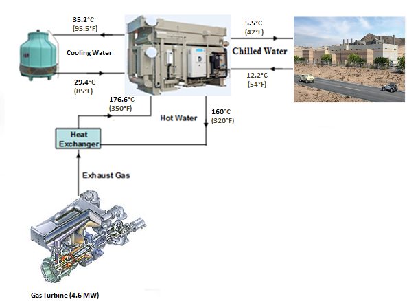
Hot water from turbine exhaust, 29 Palms military base
The exhaust of a 4.6 MW gas turbine goes to a heat exchanger, and hot water is heated to 176.6 °C and returns at 160 °C. It drives an absorption chiller. The chiller cools water for the base buildings from 12.2 to 5.5 °C, and the cooling water from the cooling tower is supplied at 29.4 and returns at 35.2 °C.
| Label on the diagram | Meaning |
|---|---|
| Gas Turbine (4.6 MW) | 4.6 MW gas turbine |
| Exhaust Gas | exhaust gases |
| Heat Exchanger | heat exchanger |
| Hot Water 176.6 °C (350 °F) / 160 °C (320 °F) | hot water at the chiller inlet and on return |
| Cooling Water 35.2 °C (95.5 °F) / 29.4 °C (85 °F) | cooling water |
| Chilled Water 5.5 °C (42 °F) / 12.2 °C (54 °F) | chilled water |
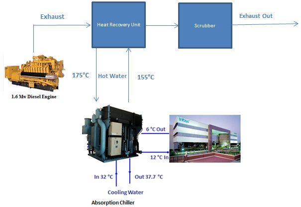
Diesel engine and heat recovery: the Infosys project
The exhaust of a 1.6 MW diesel goes to a heat recovery unit and a scrubber. Hot water circulates between the unit and the chiller at 175 and 155 °C. The chiller cools water for the building from 12 to 6 °C, and the cooling water is supplied at 32 °C and returns at 37.7 °C.
| Label on the diagram | Meaning |
|---|---|
| 1.6 Mw Diesel Engine | 1.6 MW diesel engine |
| Exhaust, Exhaust Out | exhaust, exhaust after cleaning |
| Heat Recovery Unit | heat recovery unit |
| Scrubber | scrubber |
| Hot Water | hot water |
| Absorption Chiller | absorption chiller |
| Cooling Water In / Out | cooling water at the inlet and outlet |
| 12 °C In / 6 °C Out | chilled water at the inlet and outlet |
What next?
If you found your case on a scheme, go to the page for the relevant engine. If you did not, describe your site: we will suggest the closest scheme and run the numbers. Everything inside the blue frame on the schemes, as well as the gas engines themselves, is supplied by Cold Energy (NCT). Order a feasibility study or try the calculator. NCT equipment for the cooling circuit: colden.ru.
What our customers say
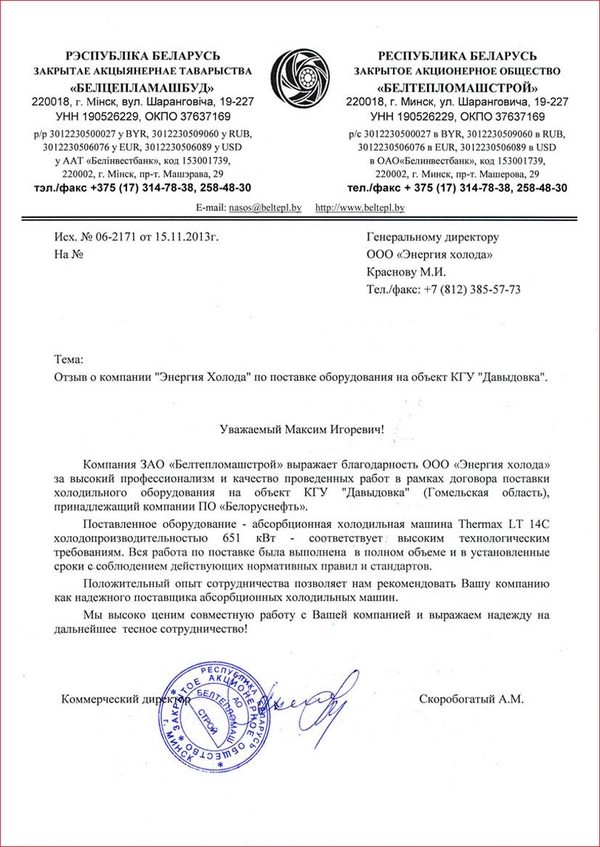
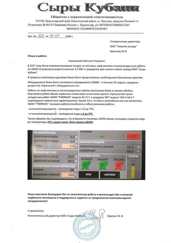
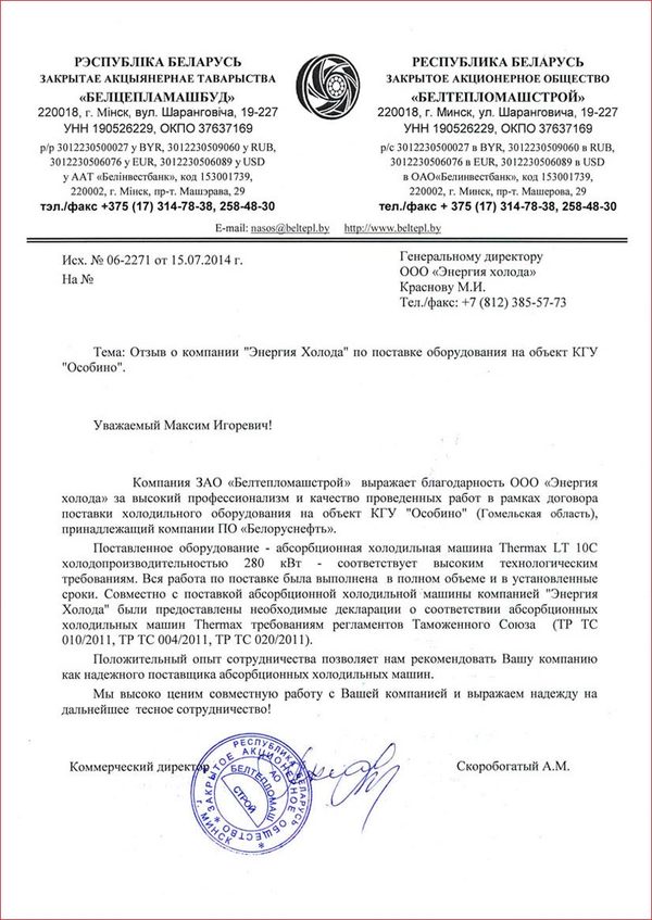
150 letters of thanks · 350+ major projects · 1,000+ customers · in business since 2011. These are real letters from customers; many others are on the references page.

Let us calculate trigeneration for your site
An engineer will put together the scheme and select the equipment, and you get a feasibility study. Free of charge, no obligation.