

Trigeneration Mistakes: Why It Fails to Pay Back
In brief. Trigeneration is most often let down by the interfaces between the engine and the cooling and by sizing that does not match the load. We cover the six interface points and the causes of failure: what happens, how it shows, and how to fix it.
Trigeneration (CCHP) fails to pay back for two groups of reasons. First, the capacity and operating hours did not match the site's real load. Second, something was not coordinated at the interface between the engine and the cooling machine, and one part gets in the way of the other. The engine and the absorption machine are each long-proven on their own. What breaks is the place where they are connected. Below are six such interface points, followed by the causes of failure from world data.
Where does trigeneration break?
The six places where mistakes happen most often lie on the boundary between generation and the cooling circuit.
Where trigeneration breaks: six interface points
Exhaust, jacket, water return, schedules, power supply, water: each interface point has its own number in the diagram.
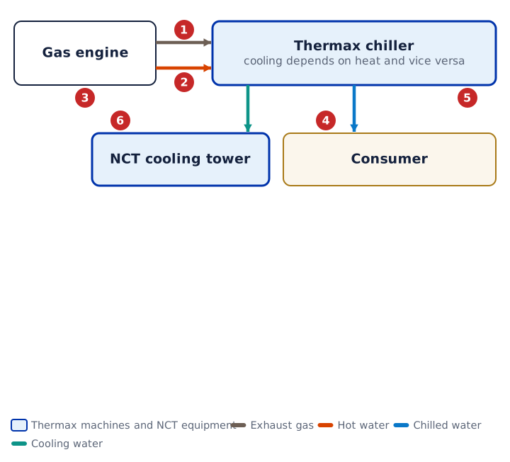
Interface 1. Exhaust back pressure
What happens. Engine exhaust passes through the machine. The machine's own gas-side resistance of 200–250 mm H2O adds up with the resistance of the flue ducts, bends, diverter damper and silencer. If the total exceeds the engine's allowable back pressure, the engine loses power.
How it shows. The electrical output of the gas engine is below its rated value precisely when the machine is running on exhaust.
How to do it right. Take from the engine datasheet the exhaust flow and temperature at 100, 75 and 50 % load and the allowable back pressure: as load drops, the exhaust gets hotter. Design the flue ducts together with Thermax using the engine datasheet. The engine always has priority. The diverter damper goes to bypass when the machine stops or power is lost; its power supply is taken from the engine.
Our site. At a gas turbine power plant in Kazakhstan, an exhaust-fired 2D 5M C machine of about 3.2 MW cools the air at the turbine inlet. The gas path diagram shows where back pressure is calculated.
Interface 2. The machine has stopped, and the jacket has nowhere to reject heat
What happens. The engine is running, but the machine has stopped: a fault, a shutdown, a closed valve. The jacket heat has nowhere to go. If the circuit is built so that the engine depends on the machine, the engine overheats.
How it shows. The engine trips on temperature, and the site loses electricity. In hot weather, when the machine is needed most, this hurts more.
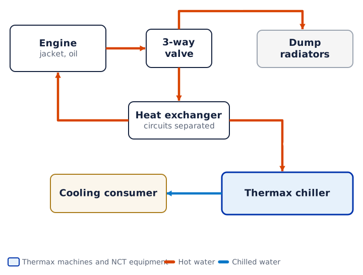
How to do it right. Separate the engine circuit from the machine circuit with a heat exchanger. A three-way valve sends the surplus to the emergency radiators, and the engine keeps running even if the machine is down.
Jacket circuit: the engine comes first
The engine circuit is separated from the machine circuit, and surplus heat goes to the emergency radiators.
Our site. The pharmaceutical plant in Pushkin: heat from the jacket water of two Jenbacher J320 gas engines goes to two Thermax TAC L5 E3 machines of 1,430 kW each. We developed the detailed design for the cooling, controls and electromechanical sections, supplied NCT equipment, and carried out installation supervision and commissioning.
Interface 3. Hot water return above the allowable limit
What happens. Water returns to the engine hotter than its datasheet allows. The engine is cooled less well and limits its output.
How it shows. By the return temperature on the panel, and by the engine limiting its output or going into protection even though the heat load on the machine is normal.
How to do it right. The return temperature is held by a three-way valve in the engine circuit. The jacket usually needs a constant flow; the engine itself requires this. On the machine side, the hot water valve is installed at the inlet and made modulating. A three-way valve at the outlet of the machine's generator is considered a mistake: control does not follow the manual, and warranty disputes follow later. The valve and actuator type are written into the specification in words. Examples of hot water modes: 90/79, 88/80, 90/75 °C.
Our site. A greenhouse complex in Sverdlovsk Region: two LT 12 C machines of 400 kW each on hot water from ten JMS 624 and four JMC 320 gas engines and a boiler house, design mode 90/80 °C, cooling 8.5/3.5 °C. The complex runs in island mode on its own gas engines.
Interface 4. The engine and the cooling run on different schedules
What happens. The engine was chosen by electrical load, while the cooling was calculated for the design peak. At part load the exhaust temperature rises and there is less heat, and the 100 % calculation stops working. Monthly cooling demand also does not match the engine load: sometimes there is surplus heat, sometimes not enough.
How it shows. Part of the exhaust goes to bypass, the emergency radiators are running, and operating hours are below design. At a US campus with a 4.5 MW turbine, up to 45 % of the exhaust was dumped to bypass on hot days and 22 % over a normal year.
How to do it right. Calculate the hourly load from 12 months of bills, not the average. Request engine data at 100, 75 and 50 %. Select the machine for the weakest design point and cover the rest of the cooling with a peak chiller. The machine's minimum load is 10 % with smooth turndown; in Trigenie, a separate generator for jacket hot water works better at engine part load. A storage tank carries the consumer while the machine takes about 30 minutes to reach operating mode.
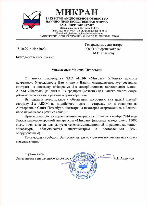
Our site. Mikran, Tomsk: a 1.7 MW gas engine and two 5G 4L C machines of 1,100 kW each. The main difficulty of the project was coordinating the gas engine plant and the absorption machines during the transition period and at low load.
Interface 5. Power loss: solution crystallization
What happens. Without power the pumps stop, and the strong lithium bromide solution stays undiluted and cools down. A 65 % solution crystallizes as early as 42 °C. The machine survives a power loss of up to 3 minutes; a longer one requires a dilution cycle. Cooling tower water that is too cold in the shoulder season leads to the same result: on a spring night it can be 5 °C, while even a double-effect machine accepts water from 10 °C.
How it shows. After a fault or on a cold night, the machine does not reach operating mode and there is no cooling.
How to do it right. A backup power feed or a UPS for the dilution cycle. On a steam machine, the valve closes on a power failure. A bypass is installed on the cooling tower: a three-way valve discharging to the basin, stroke no longer than 120 seconds, the fan off until the water at the machine inlet warms up to 20 °C, fan cut-out at 25 °C. The Thermax controller keeps a margin of at least 10 °C between the solution temperature and the crystallization temperature. The bypass and pump logic is handled by the plant controls, not by the machine.
How we do it. In the design we fix backup power for the dilution cycle and the cooling tower bypass logic in the specifications for power supply and controls; this is a rule of our design method.
Interface 6. Untreated water: scale and lost cooling
What happens. 1 mm of scale eats about 14 % of the machine's capacity and adds up to 20 % to its energy consumption. A second mistake in the same place: the cooling tower and pumps are sized as for an electric chiller. An absorption machine rejects 1.72 kW per 1 kW of cooling for a double-effect unit and 2.45 for a single-effect one, while a chiller rejects about 1.20.
How it shows. Cooling capacity drops in the first hot summer, the outlet water temperature rises, and inspection shows deposits on the tubes.
How to do it right. A make-up water analysis before selection, water treatment based on the analysis rather than a template, automatic blowdown by conductivity, sampling points on three circuits. Take the design wet-bulb temperature for the site, not for the region. A closed-circuit cooling tower keeps the machine's water clean, but gives water 2–3 °C warmer and costs more.
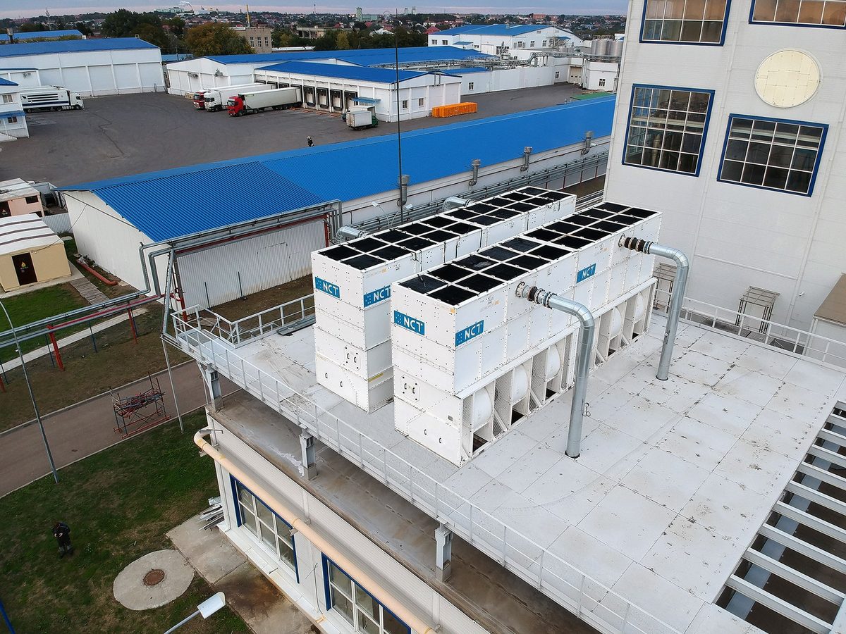
Our site. The Syry Kubani cheese plant: two NCT VR4-4-ML3-T cooling towers with a total of 8.14 MW, water 35/28 °C, and NCT W2C chemical water treatment for a 3,500 kW steam-fired Thermax absorption chiller. The plant's letter confirms that commissioning showed the declared performance and a water outlet down to 2 °C. At the pharmaceutical plant in Pushkin there are two NCT W2C water treatment units.
What other causes of failure do world studies name?
Besides the interface points, there are causes rooted in sizing and economics. They are taken from surveys and guides from the US and the UK.
| Cause | What the sources show | How it is avoided |
|---|---|---|
| Capacity chosen by electricity rather than heat | Of 85 gas CHP owners in the UK, 18 got worse results than expected; incorrect sizing is among the reasons | Size by thermal load |
| "A margin, just in case" | Oversized units stand idle when there is no heat load (manufacturer's view) | Size by base load |
| No year-round heat demand | The heat load must match the plant's output throughout the year | Give the heat a summer job: cooling |
| Too few operating hours | Fewer than 3,000 hours a year usually does not justify the investment (US) | At least 3,000–4,000 hours |
| Part-load operation | Efficiency "drops significantly at part load" | Reciprocating engines and a peak chiller |
| Small spread between gas and electricity prices | An acceptable return needs a spread of about 2 cents per kWh | Calculate at current prices |
| The market changed, the heat consumer closed | Heat revenue fell to zero | Do not count on selling heat to third parties in the payback |
| Design, installation and service underestimated | Cheap engines broke down; an expensive service contract paid for itself | One contractor for cooling and service |
| Specifics of absorption | Small machines are expensive; the cooling tower is larger than for a chiller | Consider a machine from 300 kW |
| Calculation "on paper" | Average values are not enough; an hourly model is needed | Hourly profiles for 12 months |
There is no single trigeneration failure rate in public data. The only estimate, 18 out of 85, refers to gas CHP plants in the UK and to a small sample.
There are also design mistakes that surface during installation. Condensate to the sewer: at 3.5 t/h this means losing 326 kW and all the treated water. GOST flanges on ASME nozzles: they do not fit together. Pressure at the nozzles above 8 kgf/cm² in a tall building: the water boxes fail. Gas consumption "we'll find out later": the allocation is refused after the design is done. A machine in an unheated room: it freezes, because it is filled with water. Comparison by machine price rather than total cost.
What follows from this, and who should be responsible for the interface?
Each of the six interface points lies between the engine and the cooling: the exhaust and jacket belong to the engine, while the water, valves and cooling tower belong to the cooling circuit. If the engine and the cooling are split between different contractors, each has its own datasheet and its own contract clause. Back pressure, water return, schedule and power supply end up belonging to "no one."
That is why trigeneration can be done reliably by those who are responsible for the interface between generation and cooling and have the equipment for the cooling circuit. Cold Energy (NCT) is the official representative of Thermax in Russia and the CIS; Thermax has more than 8,300 cooling and heating installations worldwide. In Russia and the CIS, Thermax machines are supplied only by Cold Energy. NCT cooling towers, chillers and dry coolers, design, installation supervision, commissioning and service of the cooling circuit are all in one company with us. So you can order gas engines, the cooling circuit and the interface between them from one company.
We also show the opposite. If the cooling load is below 300 kW or it is needed for less than 2,000 hours a year, an absorption machine will not pay back, and we will tell you so right away. For how to calculate, see the "Feasibility study" section. Our sites are collected in the "Projects" section, and the general operating principle is explained on the "Trigeneration" page.
Want to check your project against these six interface points? Order a feasibility study or estimate the payback in the calculator. About the equipment: Thermax absorption chiller.
Sources
- DECC (UK), Factors affecting the uptake of gas CHP, December 2014: https://assets.publishing.service.gov.uk/media/5a7ef55240f0b62305b843e9/Factors_affecting_the_uptake_of_gas_CHP_Final_v6.pdf
- Stoddart (SenerTec), The importance of not over-sizing CHP, 2016: https://modbs.co.uk/news/fullstory.php/aid/16058/The_importance_of_not_over-sizing_CHP.html
- Sclafani, Beyene, Sizing CCHP Systems for Variable and Non-coincident Loads, 2008: https://journals.riverpublishers.com/index.php/DGAEJ/article/view/14191
- Merrick, Elsner (BYU-Idaho), From Cogen to Trigen, APPA 2019: https://rma.appa.org/wp-content/uploads/2019/09/RMA-2019_1-4-From-Cogen-to-Trigen.pdf
- ORNL / DOE CHP TAP, CHP Project Screening, 2022: https://bptraining.ornl.gov/wp-content/uploads/2022/12/Session-2-CHP-Project-Screening-2022-12-01-FINAL.pdf
- DOE, CHP Resource Guide for Hospital Applications, 2007: https://www.energy.gov/sites/prod/files/2013/11/f4/chp_hospital_guidebook_2007.pdf
- DOE, Absorption Chillers for CHP Systems, DOE/EE-1608, 2017: https://www.energy.gov/sites/prod/files/2017/06/f35/CHP-Absorption%20Chiller-compliant.pdf
- EPA, Using the EPA CHP Screening Tool, 2019: https://19january2021snapshot.epa.gov/sites/static/files/2019-05/documents/chp_screening_tool.pdf
- EPA, Catalog of CHP Technologies, September 2017: https://www.epa.gov/sites/default/files/2015-07/documents/catalog_of_chp_technologies.pdf
Frequently asked questions
What flue resistance is allowable for a gas-fired absorption chiller?
Less than 5 mm H2O at the machine outlet. The stack is designed so that it removes the gases on its own: velocity 3.6–4.6 m/s, design temperature at least 360 °C with flue gas leaving at 190 °C, condensate only through a water seal. For every 300 mm of horizontal run, 180 mm is added to the stack height, and for every 90° bend another 1.2 m. A long flue with such bends leaves the burner short of full output.
How do you back up exhaust-fired absorption chillers when the gas generator stops?
A built-in burner makes up the shortfall; just include its consumption in the allocation request from the start. A standalone gas-fired absorption chiller covers the remainder and in winter heats water to 95 °C on its own.
What our customers say
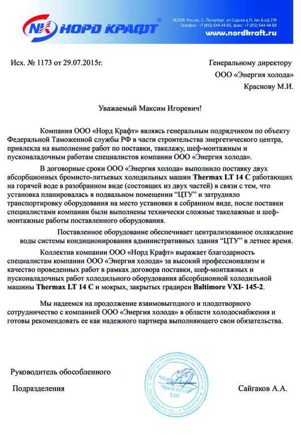
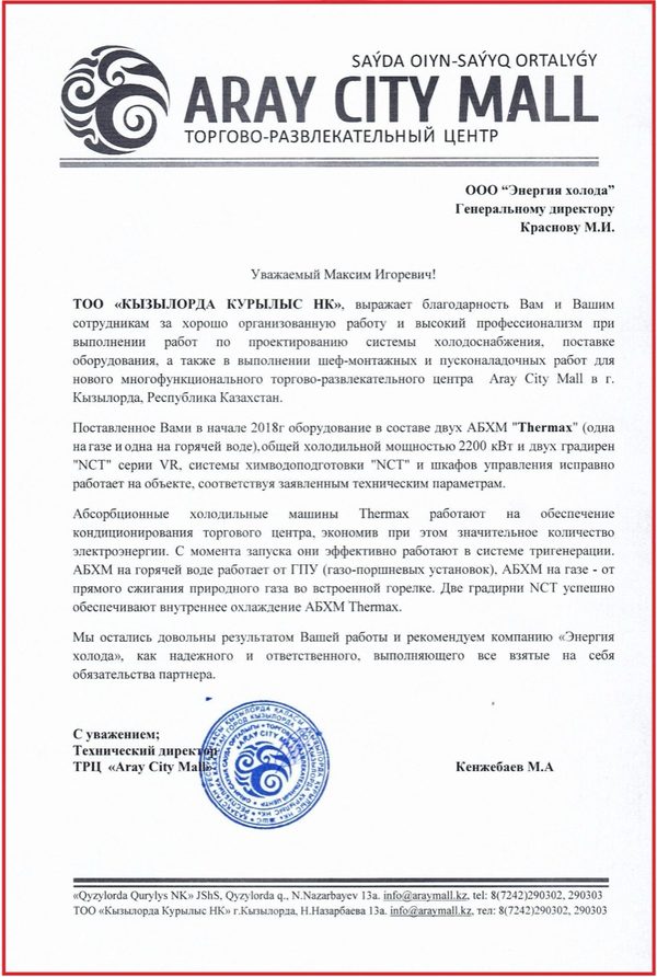
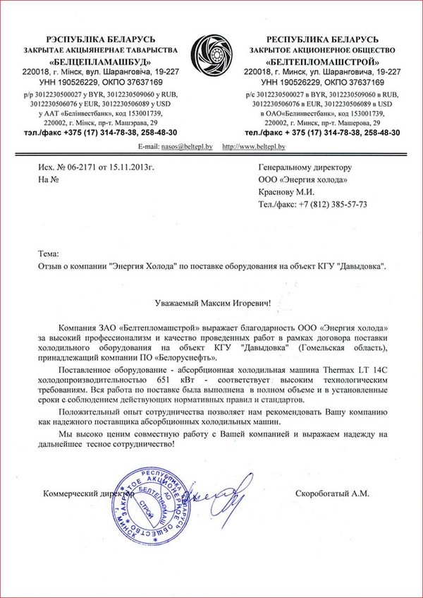
150 letters of thanks · 350+ major projects · 1,000+ customers · in business since 2011. These are real letters from customers; many others are on the references page.
Let us calculate trigeneration for your site
An engineer will put together the scheme and select the equipment, and you get a feasibility study. Free of charge, no obligation.